
- Actuators
- Adapters
- Air Blowers
- Air Conditioners
- Air Curtains
- Air Purifiers
- Anemometers
- Axial fans
- Ball Valves
- Belimo
- Blowers
- Brackets
- Brass
- Brazing Rods
- Capacitors
- Carrier Parts
- Clamp Meters
- Cleaning Products
- Coatings
- Compressors
- Condensate Pumps
- Connectors
- Contactors
- Copper Capillary
- Copper Coils
- Copper Straight Tubes
- Copper Strainers
Johnson Controls T7200-TB21-9JS0 Thermostat Wiring Diagrams & Terminal Mapping


Johnson Controls T7200-TB21-9JS0 Thermostat Wiring Diagrams & Terminal Mapping
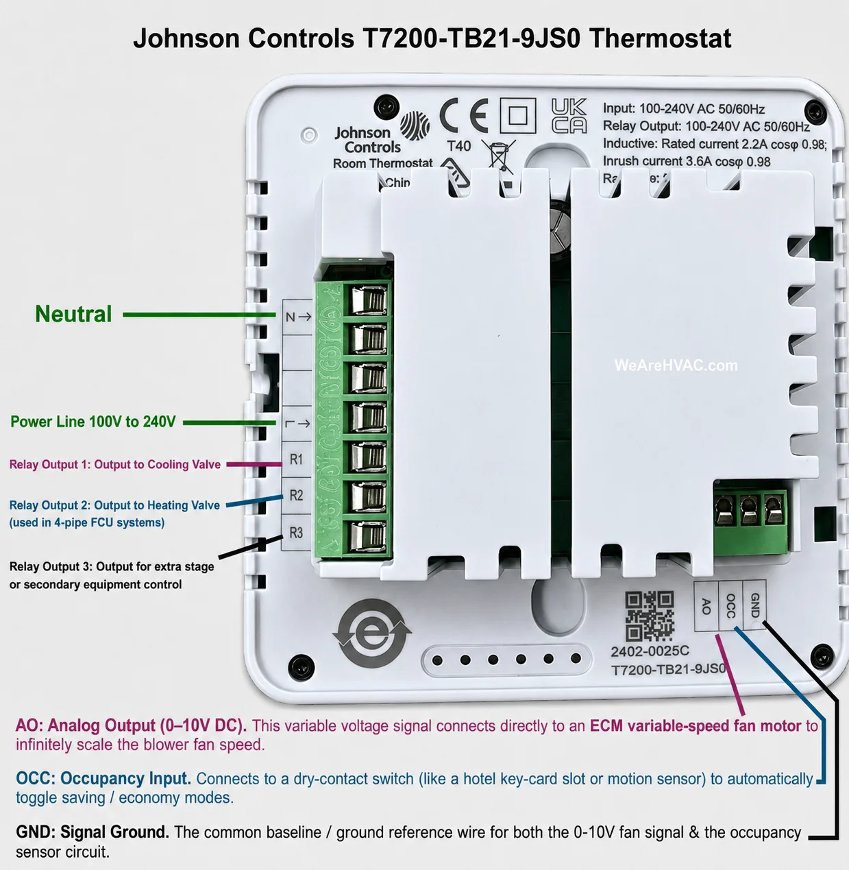
Main Power & Output Terminal Block (Left Green Block)
- N: Neutral Line Input.
- L (Arrow pointing in): Line/Hot Power Input (100–240V AC).
- R1: Relay Output 1 (Typically assigned to the cooling valve).
- R2: Relay Output 2 (Typically assigned to the heating valve in a 4-pipe system configuration).
- R3: Relay Output 3 (Auxiliary stage/secondary device control).
Low Voltage Control Block (Bottom Right Pins)
- AO: Analog Output (Provides the 0–10V DC variable voltage signal to control electronically commutated ECM fan motor speeds smoothly).
- OCC: Occupancy Input (Dry-contact terminal used for automated energy-saving triggers via hotel key cards or motion sensors).
- GND: Signal Ground (The shared baseline/reference ground for your low-voltage control signals).
Did You Know?
We carry an extensive range of Johnson Controls thermostats. Click here to find out more https://wearehvac.com/johnson-controls-thermostats/