- Actuators
- Adapters
- Air Blowers
- Air Conditioners
- Air Curtains
- Air Purifiers
- Anemometers
- Axial fans
- Ball Valves
- Belimo
- Blowers
- Brackets
- Brass
- Brazing Rods
- Capacitors
- Carrier Parts
- Clamp Meters
- Cleaning Products
- Coatings
- Compressors
- Condensate Pumps
- Connectors
- Contactors
- Copper Capillary
- Copper Coils
- Copper Straight Tubes
- Copper Strainers
Understand Johnson Controls Thermostats More

Understand Johnson Controls Thermostats More
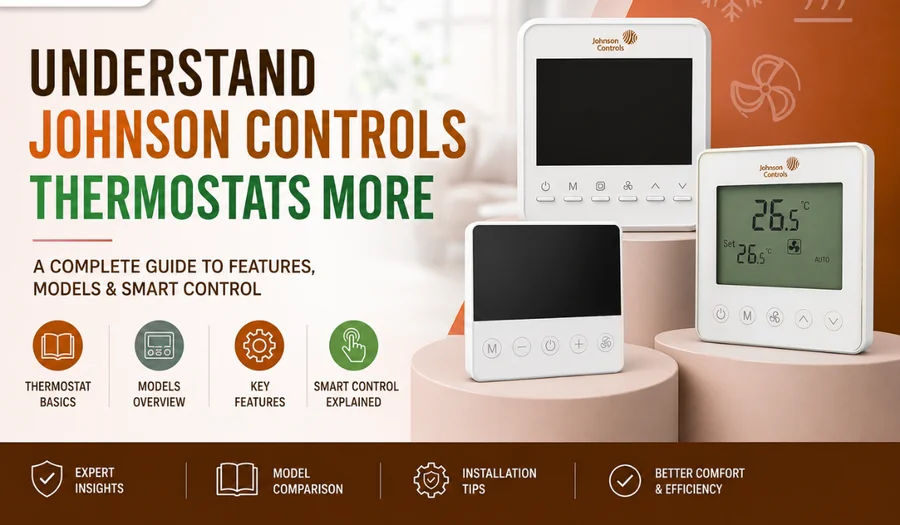
When evaluating the entire line of Johnson Controls Digital Thermostats, devices are grouped into distinct series categorized by display type, interface design, fan hardware limitations, and communication capabilities.
The breakdown of the differences across all of these related models includes:
1. Interface & Design Generation
- T9000 Series (e.g., T9200 ): This is the flagship premium tier. It features a large, glass-front frameless capacitive touchscreen with modern integrated lighting. There are no moving mechanical buttons.
- T8000 Series (e.g., T8600 ): This sits in the mid-to-high tier. It bridges generations by providing a crisp, backlit touchscreen interface, but uses a more traditional framed rectangular casing rather than a glass-edge appearance.
- T7000 Series (e.g., T7200, T7600 ): This is the classic utility/workhorse standard. It features a segmented LCD display paired with individual, physical tactile push buttons directly under the screen area.
Fan Integration (The “TB21” vs. “TF20” Suffix)
The suffix within the model number indicates how the internal relays control air movement:
- TB21 Models (e.g., T9200-TB21, T7200-TB21 ): These models feature a dedicated 0–10V DC Analog Output (AO) terminal. This allows precise modulating speed control for high-efficiency electronically commutated motors (ECM fans) or modulating valves.
- TF20 Models (e.g., T9200-TF20, T7200-TF20 ): These models focus on traditional 3-speed fan relay switches. They step mechanically through fixed Low, Medium, and High relays to speed up or slow down a standard AC induction fan.
3. Application Differences
Even within the exact same series, individual units are mapped to specific HVAC equipment configurations based on the termination layout:
| Model Variant | Screen Type | Local Fan Relay Control | Proportional Control (0–10V) | Typical HVAC Integration |
| T9200-TB21-1JS0 | Frameless Touch | Single-speed fan loop | Yes (Dedicated AO terminal) | Premium ECM Fan Coil Units (FCU), Modulating Valved systems |
| T9200-TF20-1JS0 | Frameless Touch | 3-Speed mechanical relays | No | Standard 2-pipe / 4-pipe multi-speed commercial Fan Coils |
| T7200-TB21-9JS0 | Segmented LCD / Physical Buttons | 3-Speed mechanical relays | Yes (Dedicated AO terminal) | Dual-compatibility systems (supports 3-speed or ECM analog outputs) |
| T7200-TB20-9J00 | Segmented LCD / Physical Buttons | 3-Speed mechanical relays | No | Standalone standard AC Fan Coil Units without automation telemetry |
4. Integration Protocol (“JS0” vs “9JS0” series)
- Modbus Integration: Models containing an “S” indicator support native serial integration protocols. They allow localized network strings to relay system ambient conditions directly back into commercial Building Management Systems (BMS).
- Standalone: Base models without communication letters function as isolated wall sensors controlling equipment exclusively using local terminal outputs.
Comprehensive Comparison Matrix (Ascending Order)
| Model Number | Screen & Interface | Hardware Fan Control Relay | Analog Output (0–10V DC) | BMS Protocol Support | Best-Suited Applications |
| T7200-TB20-9J00 | Segmented Backlit LCD with Push Buttons | 3-Speed Relays (Low, Med, Hi) | No | None (Standalone) | Cost-effective, independent room cooling or floor heating installations. |
| T7200-TB21-9JS0 | Segmented Backlit LCD with Push Buttons | 3-Speed Relays (Low, Med, Hi) | Yes (Dedicated AO) | Modbus Protocol Included | High-utility commercial projects requiring dual-control flexibility. |
| T7200-TF20-9JS0 | Segmented Backlit LCD with Push Buttons | 3-Speed Relays (Low, Med, Hi) | No | Modbus Protocol Included | Standard utility multi-speed fan coil units tied to a master BMS loop. |
| T8000 Series (e.g., T8200) | Framed Touchscreen Display | 3-Speed Relays (Max 5A Resistive) | Variant Dependent | Modbus / Standalone Mix | Mid-to-high tier office zones and hospitality suites tracking active timers. |
| T9200-TB21-1JS0 | Frameless Capacitive Glass Touchscreen | Single-Speed Only | Yes (Dedicated AO) | Modbus Protocol Included | Premium buildings with ECM modulating fan coil units (FCU). |
| T9200-TF20-1JS0 | Frameless Capacitive Glass Touchscreen | 3-Speed Relays (Low, Med, Hi) | No | Modbus Protocol Included | Premium buildings with standard 3-speed AC fan coil motors. |
Key Takeaway for Part Numbers
- Prefix (T9 vs T7 vs T8 ): Dictates display aesthetics and button styles.
- Middle Code (TB21 vs TF20 ): Defines signal output. TB21 models give you a dedicated 0–10V line to smoothly throttle modulating valves or variable ECM motors.
- TF20 models are physically hardwired with stepping steps exclusively for fixed 3-speed fan setups.
- Suffix (JS0 / 9JS0 vs J00): Indicates presence of communication lines. “S” sub-models link directly into building automation networks.
AO – Analog Output Terminal
On a thermostat terminal block, AO stands for Analog Output.
Unlike a standard On/Off relay switch that can only be turned fully on or fully off, the AO terminal provides a variable voltage signal ranging anywhere from 0V to 10V DC.
How the AO Wire Controls Equipment
The thermostat varies the output voltage to modulate or “throttle” compatible commercial HVAC components based on the exact temperature needs of the room:
- 0V to 2V Signal: Equipment is off or at minimum capacity.
- 5V Signal: Equipment runs at exactly 50% capacity.
- 10V Signal: Equipment ramps up to full 100% capacity.
What Components Connect to AO?
According to the official Johnson Controls Thermostat Documentation, this variable control is typically wired to one of two main components:
- Modulating/Proportional Valves: Instead of opening and closing rapidly (which creates temperature swings), a 0–10V valve opens partially (e.g., 35% open) to let a precise stream of chilled or hot water pass through the system continuously.
- ECM Fan Speed Controls: Instead of stepping abruptly between fixed Low, Medium, and High clicks, the AO terminal talks directly to an Electronically Commutated Motor (ECM). The fan ramps up or down fluidly, running quietly at the exact speed required to maintain comfort.
Critical Wiring Rules for AO
- Requires a Ground Reference: An analog output signal cannot function over a single wire. You must always run a pair of low-voltage wires: the signal line goes to AO and the common /return line must land on GND.
- Keep Isolated from Mains Voltage: Do not run your low-voltage AO signal wire in the same conduit, track, or tightly bundled harness as high-voltage AC wires (L and N).
- High AC voltages will bleed interference into the 0–10V DC line, causing the valve or fan to twitch or fail.
OCC – Occupancy Input Terminal
On a thermostat terminal block, OCC stands for Occupancy Input (often referred to in commercial HVAC as a Binary Input or Dry Contact Input).
It allows the thermostat to switch between its normal Occupied mode (comfortable heating / cooling when people are present) and an energy-saving Unoccupied mode (setback temperatures when the room is empty).
How the OCC Terminal Works
The OCC terminal is a low-voltage “dry contact” loop. It does not send voltage out; instead, it watches for an external switch to close or open the electrical circuit between the OCC terminal and the GND (Ground) terminal.
- Circuit Closed: The thermostat detects that the room is occupied and runs standard comfort settings.
- Circuit Open: The thermostat switches to setback or eco mode to save electricity.
Typical Devices Connected to the OCC Terminal
- Hotel Card-Key Switches: In hospitality settings, sliding a plastic room key card into the wall slot closes the circuit, waking up the air conditioning. Removing the card opens the circuit, reverting the room to an eco-setback mode while the guest is out.
- Ceiling-Mounted Motion Sensors (PIR or Passive Infrared Sensor): A commercial motion detector can monitor a conference room or office. If no movement is seen for a set duration (e.g., 30 minutes), the sensor opens the contact to turn down the HVAC.
- Window or Balcony Door Contacts: In many resorts, a magnetic sensor is installed on exterior doors. If a guest leaves the balcony door open to the outside air, the OCC contact breaks, instantly disabling the local fan coil unit so it doesn’t waste energy trying to cool the outdoors.
- Master Time Clocks: A central automation timer or scheduler can open and close this loop to shift entire office zones into night-purge or weekend-idle modes.
Key Wiring Rule
- No External Voltage: Never apply 24V AC or 230V mains power directly to the OCC wire. It is purely designed for clean, unpowered relay switches.
- Accidentally applying live voltage to this signal terminal will permanently melt or short out the thermostat’s internal processor board.