
- Actuators
- Adapters
- Air Blowers
- Air Conditioners
- Air Curtains
- Air Purifiers
- Anemometers
- Axial fans
- Ball Valves
- Belimo
- Blowers
- Brackets
- Brass
- Brazing Rods
- Capacitors
- Carrier Parts
- Clamp Meters
- Cleaning Products
- Coatings
- Compressors
- Condensate Pumps
- Connectors
- Contactors
- Copper Capillary
- Copper Coils
- Copper Straight Tubes
- Copper Strainers
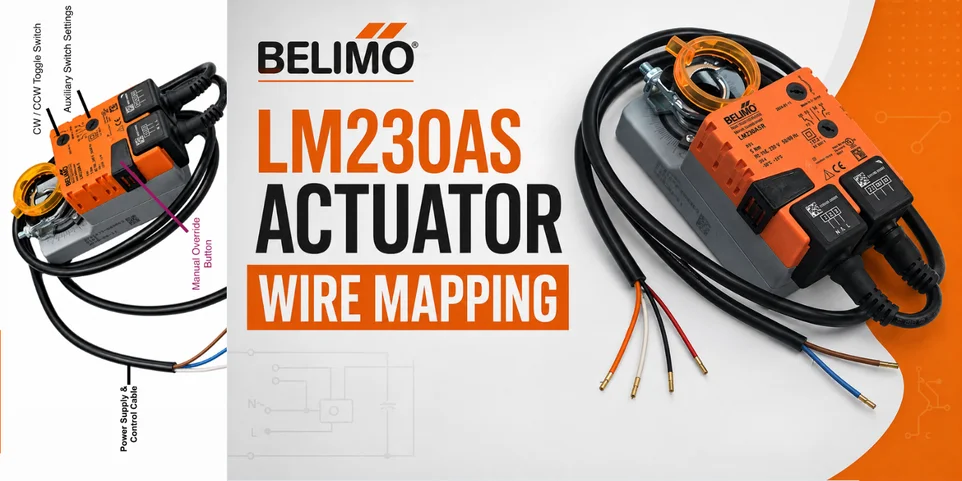
Belimo LM230A-S actuator Wire Mapping

Belimo LM230A-S actuator Wire Mapping
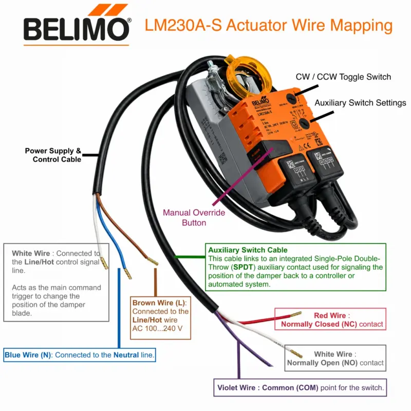
The Belimo LM230A-S damper actuator uses two separate integrated cables: one for the main AC power/control input and one for the internal auxiliary switch.
Below is the complete wire color mapping and connection diagram based on the official Belimo Technical Datasheet.
1. Power Supply & Control Cable
This cable provides the mains voltage power (AC 100…240 V) to operate the motor.
- Blue Wire (N): Connected to the Neutral line.
- Brown Wire (L): Connected to the Line/Hot wire for primary direction or power.
- White Wire : Connected to the Line/Hot control signal line.
2. Auxiliary Switch Cable
This cable links to an integrated Single-Pole Double-Throw (SPDT) auxiliary contact used for signaling the position of the damper back to a controller or automated system.
- Violet Wire : Common (COM) point for the switch.
- Red Wire : Normally Closed (NC) contact.
- White Wire : Normally Open (NO) contact.
(Note 1: The internal switch can be manually adjusted via the orange rotary knob on the front face of the actuator to trigger anywhere between 0% and 100% of the rotation stroke.
Note 2: A Single Pole Double Throw (SPDT) switch is an electrical switch that routes one input signal to one of two separate outputs. It acts like a changeover switch, connecting a single common terminal to either terminal A or terminal B, but never both at the same time.)
Difference between LM230A-S and LM230ASR
The Belimo LM230ASR actuator uses a completely different control mechanism and wire mapping compared to the LM230A-S. While the LM230A-S is a digital open/close or 3-point floating actuator with a built-in auxiliary switch, the LM230ASR is a modulating (proportional) actuator that is controlled via a DC voltage signal and lacks the integrated auxiliary switch.
The mapping differences based on the official Belimo Technical Datasheets break down as follows:
Cable Layout Comparison
- LM230A-S: Uses two separate 3-wire cables (one for power/control, one for auxiliary switches).
- LM230ASR: Uses one 2-wire power cable and one 4-wire control/feedback signal cable.
Structural Wire Mapping Differences
| Terminal / Feature | LM230A-S (Open/Close & Floating) | LM230ASR (Modulating 2…10 V) |
| Control Signal Type | Line Voltage Switched (AC 100…240 V) | Proportional Low-Voltage (DC 2…10 V) |
| Power Supply (N) | Blue Wire (Neutral) | Blue Wire (Neutral) |
| Power Supply (L) | Brown Wire (Line/Hot) | Brown Wire (Line/Hot) |
| Signal Input (Y) | White Wire (Line voltage control input) | White Wire (DC 2…10 V command signal) |
| Position Feedback (U) | Not available | Orange Wire (DC 2…10 V feedback output) |
| Auxiliary Reference | Not available | Red Wire (DC 24 V, max 10 mA auxiliary supply) |
| Reference Common | Not available | Grey Wire (Signal reference ground / Neutral) |
| Auxiliary Switch Wiring | Violet, Red, White | None (No integrated switch on standard ASR) |
Key Operational Differences
- Modulating Input (Y): On the LM230ASR, the white wire takes a precision DC 2…10 V control signal from a programmable controller instead of a raw line-voltage power feed. The voltage value dictates the exact degree angle of the damper blade (e.g., 2 V is fully closed, 6 V is 50% open, and 10 V is fully open).
- Position Feedback Output (U): The LM230ASR transmits an analog position signal back to the automation network via its Orange Wire. This lets the Building Management System (BMS) monitor the real-time physical angle of the damper.
- Internal Auxiliary Voltage: The LM230ASR includes a specialized Red
Wire that outputs a small DC 24 V auxiliary current. This is typically used to drive simple external positioners or low-power field sensors directly from the actuator.