

- Actuators
- Adapters
- Air Blowers
- Air Conditioners
- Air Curtains
- Air Purifiers
- Anemometers
- Axial fans
- Ball Valves
- Belimo
- Blowers
- Brackets
- Brass
- Brazing Rods
- Capacitors
- Carrier Parts
- Clamp Meters
- Cleaning Products
- Coatings
- Compressors
- Condensate Pumps
- Connectors
- Contactors
- Copper Capillary
- Copper Coils
- Copper Straight Tubes
- Copper Strainers
Belimo EXT-CF24-D202-AF terminal mapping


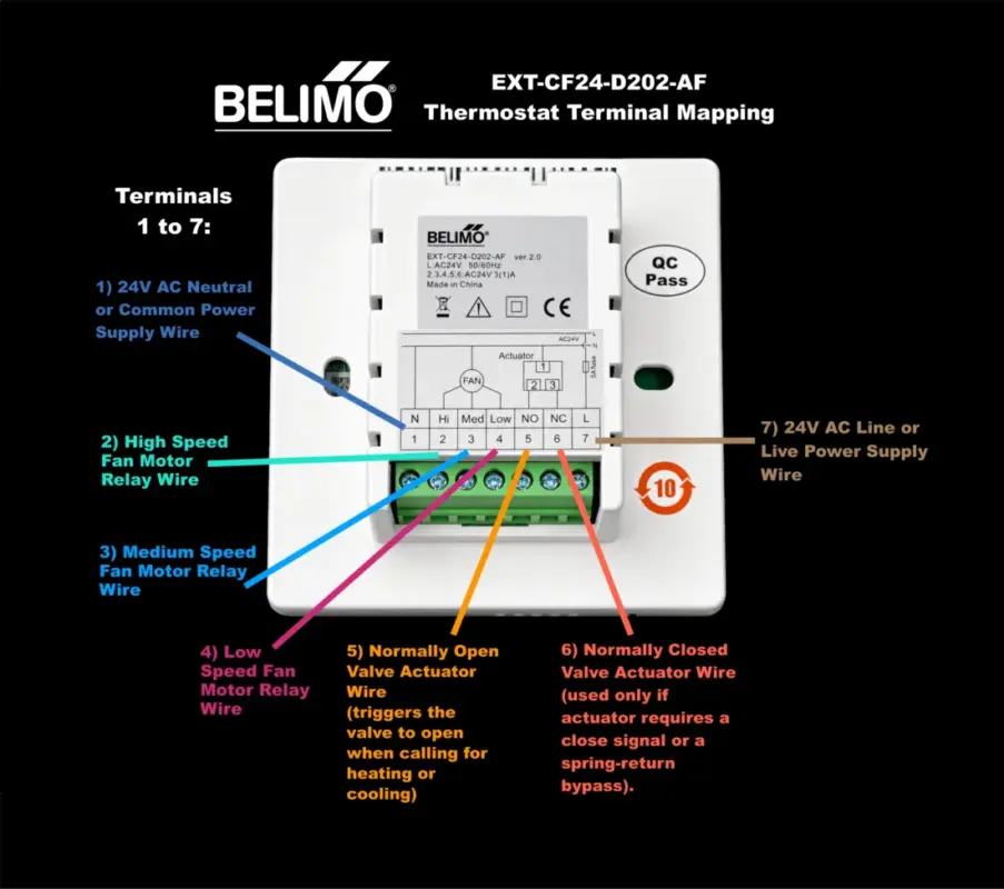
Belimo EXT-CF24-D202-AF terminal mapping
To wire the Belimo EXT-CF24-D202-AF thermostat, match your system wires to the corresponding numbers on the green terminal block. This unit operates strictly on 24V AC power (not mains voltage).
Always shut off the circuit breaker before beginning electrical installation.
Terminal Wiring Reference
- Terminal 1 (N): Connect the 24V AC Neutral / Common power supply wire.
- Terminal 2 (Hi): Connect the High-speed fan motor relay wire.
- Terminal 3 (Med): Connect the Medium-speed fan motor relay wire.
- Terminal 4 (Low): Connect the Low-speed fan motor relay wire.
- Terminal 5 (NO): Connect the Normally Open valve actuator wire (triggers the valve to open when calling for heating or cooling).
- Terminal 6 (NC): Connect the Normally Closed valve actuator wire (used only if your actuator requires a close signal or a spring-return bypass – see below to understand spring return bypass.
- Terminal 7 (L): Connect the 24V AC Line / Live power supply wire.
Special Note: The built-in onboard 5A fuse protects the internal 24V Live line entering terminal 7.
Note on above terminal 1 (N):
The 24V AC Neutral / Common wire (usually labeled C in other thermostats) is the return path that completes the electrical circuit, allowing constant 24-volt power to flow and continuous power to run your thermostat’s screen and internal electronics.
Think of it as the exit route for electricity after the active “Hot” wire delivers the power.
Why It Matters
- Completes the Circuit: Electricity must flow in a loop; the Hot wire (Terminal 7) brings the power in, and the Common wire (Terminal 1) carries it back out.
- Constant Power: Older thermostats used batteries, but smart or digital thermostats like this Belimo require a constant stream of electricity to keep the LCD screen lit.
- No Shock Hazard: Even though it is called “Neutral” or “Common,” it is part of a low-voltage (24V) system, meaning it is much safer than the 110V/230V mains voltage found in standard wall outlets.
Source of the wire: This wire originates directly from the “C” or “COM” terminal on your HVAC equipment’s internal 24V transformer (often located inside your furnace, air handler, or fan coil unit).
General Step-by-Step Installation
- Separate the Housing: Use a small flathead screwdriver to gently release the plastic clips holding the front control panel to the back base plate.
- Route and Prepare Wires: Pull your 24V HVAC control wires through the rear opening of the base plate. Strip roughly 6 mm (1/4 inch) of insulation off each wire strand.
- Secure Wires: Loosen the screw for each target terminal slot, insert the bare copper wire fully, and tighten the screw firmly. Ensure no stray copper strands touch adjacent terminals.
- Mount and Reassemble: Secure the back plate to your wall junction box using the provided mounting screws. Align the connection pins, then press the front LCD faceplate back onto the base until it clicks into place.
What is a Spring Return Bypass?
A spring return bypass is a mechanical safety system that uses a built-in spring to automatically close (or open) a bypass valve when power, pressure, or signal control is lost.
How It Works
- Active State: An actuator (electric, pneumatic, or hydraulic) forces the valve open against a powerful internal spring to allow fluid or gas to bypass a system component.
- Failsafe State: If power fails or an operator releases the control lever, the mechanism loses its forcing power.
- Spring Return: The compressed spring instantly pushes the valve back to its original, safe position without needing any electricity or manual intervention.
Common Real-World Uses
HVAC Systems: Protects heating and cooling coils from freezing or over-pressurizing by rerouting water flow if power cuts out.