

- Actuators
- Adapters
- Air Blowers
- Air Conditioners
- Air Curtains
- Air Purifiers
- Anemometers
- Axial fans
- Ball Valves
- Belimo
- Blowers
- Brackets
- Brass
- Brazing Rods
- Capacitors
- Carrier Parts
- Clamp Meters
- Cleaning Products
- Coatings
- Compressors
- Condensate Pumps
- Connectors
- Contactors
- Copper Capillary
- Copper Coils
- Copper Straight Tubes
- Copper Strainers

Belimo LM230A Actuator Terminal Mapping

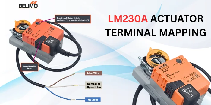
Belimo LM230A Actuator Terminal Mapping
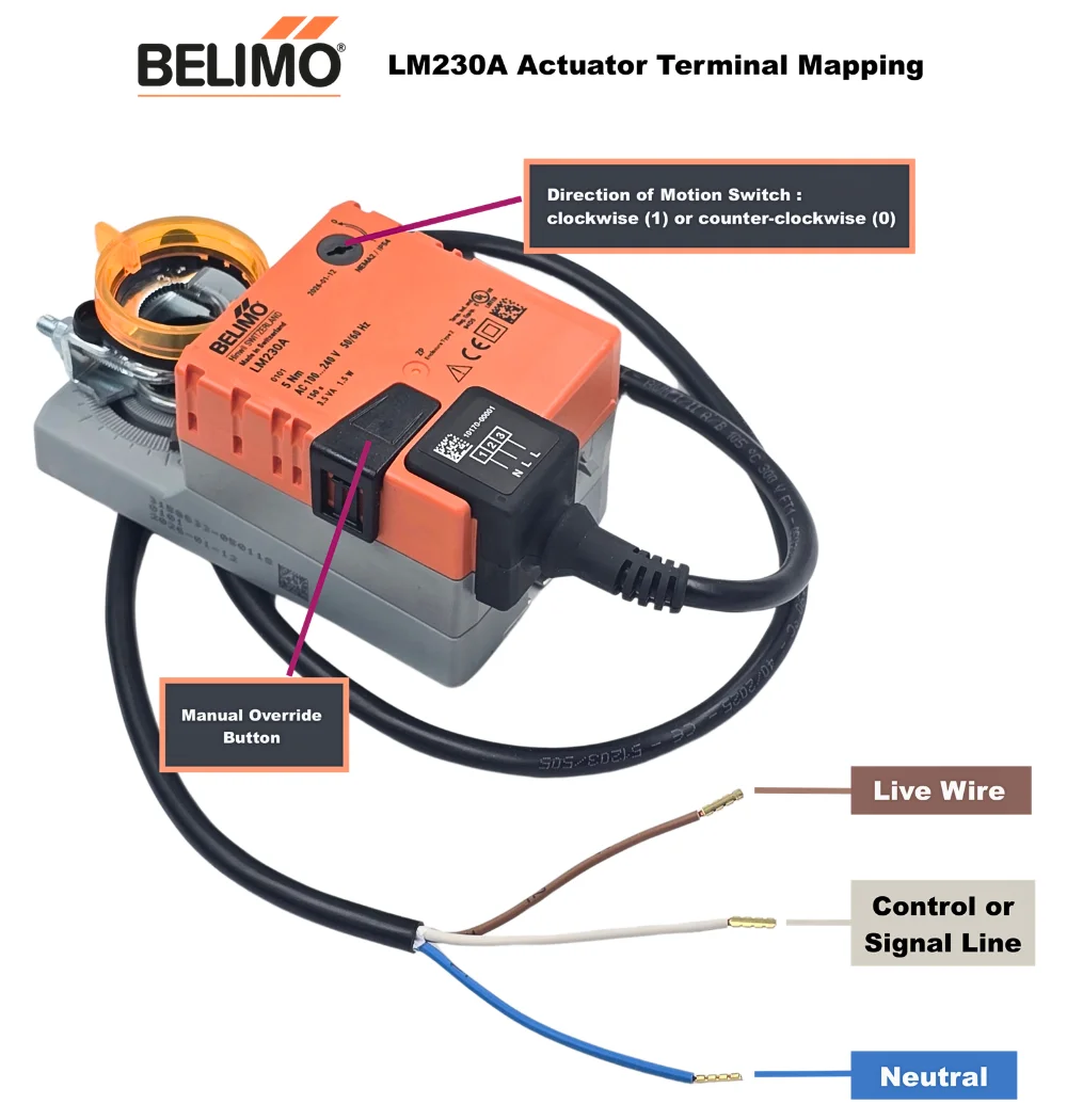
The Belimo LM230A is a line-voltage damper actuator operating at AC 100…240V. It features a 3-wire connection that can be wired for either Open/Close (2-point) control or 3-point (floating) control.
To read more about 3-point (floating) control, please click here: https://wearehvac.com/3-point-floating-control-in-hvac/
The three wires correspond directly to the schematic labeled on the product plug (1, 2, and 3):
- Wire 1 (Blue): Neutral (N)
- Wire 2 (Brown): Live / Line (L)
- Wire 3 (White): Control / Signal Line (L) [1]
Wiring Method 1: Open / Close Control (2-Point)
Use this setup if you want the actuator to fully drive open when a single switch (like a thermostat or relay) closes, and drive back to its original position when the switch opens.
- Connect the Blue wire (1) directly to the permanent Neutral (N) line.
- Connect the Brown wire (2) directly to the permanent Live (L) line.
- Route the White wire (3) through your control switch/relay contact, connecting it to the Live (L) line.
- Switch Open: The actuator turns to its resting position.
- Switch Closed: The actuator powers up and drives to the opposite end position.
Wiring Method 2: 3-Point Control (Floating)
Use this setup if your controller has separate command paths for opening and closing, or if you need to stop the damper at mid-way intervals.
- Connect the Blue wire (1) directly to the permanent Neutral (N) line.
- Connect the Brown wire (2) to the “Close” or counter-clockwise command line (Live).
- Connect the White wire (3) to the “Open” or clockwise command line (Live).
- Power on Wire 2 only: Actuator turns in direction 0.
- Power on Wire 3 only: Actuator turns in direction 1.
Important Setup Steps
- Direction Switch: Look under the black rubber cover on the top face of the actuator to find the
0 / 1direction switch. This sets whether the motor turns clockwise or counterclockwise when receiving a signal. - Manual Override: If you need to manually turn the actuator during installation, press and hold the black push-button located on the top cover to disengage the gear train.