

- Actuators
- Adapters
- Air Blowers
- Air Conditioners
- Air Curtains
- Air Purifiers
- Anemometers
- Axial fans
- Ball Valves
- Belimo
- Blowers
- Brackets
- Brass
- Brazing Rods
- Capacitors
- Carrier Parts
- Clamp Meters
- Cleaning Products
- Coatings
- Compressors
- Condensate Pumps
- Connectors
- Contactors
- Copper Capillary
- Copper Coils
- Copper Straight Tubes
- Copper Strainers
Belimo LM230ASR actuator Wire Mapping

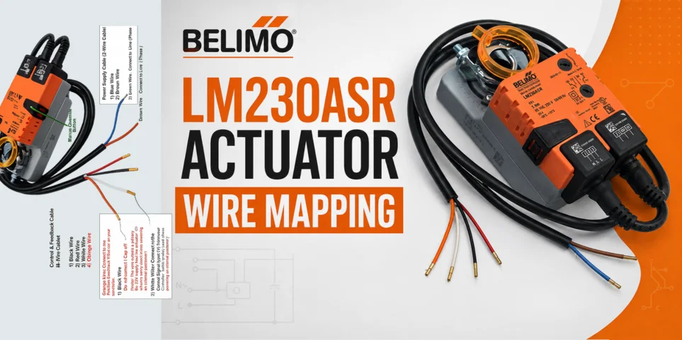
Belimo LM230ASR actuator Wire Mapping
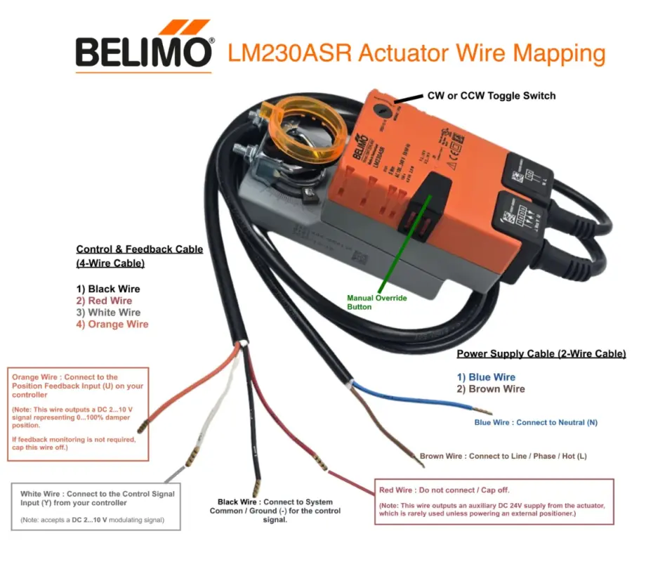
To wire the Belimo LM230ASR modulating damper actuator properly, you need to handle two separate pre-installed cables: the Power Supply Cable (2-wire) and the Control/Signal Cable (4-wire).
Safety Warning
This device operates on high voltage (AC 100…240 V). Always ensure the main power supply is completely turned off at the breaker before stripping or connecting any wires.
1. Power Supply Cable (2-Wire Cable)
This cable provides mains power to the actuator. Connect it to your AC source as follows:
- Blue Wire : Connect to Neutral (N).
- Brown Wire : Connect to Line / Phase / Hot (L).
2. Control & Feedback Cable (4-Wire Cable)
This cable connects to your controller or Building Management System (BMS) to handle the 2…10 V modulating command and position feedback. Connect it as follows:
- Black Wire : Connect to System Common / Ground (-) for the control signal.
- Red Wire : Do not connect / Cap off. (Note: This wire outputs an auxiliary DC 24V supply from the actuator, which is rarely used unless powering an external positioner).
- White Wire : Connect to the Control Signal Input (Y) from your controller (accepts a DC 2…10 V modulating signal).
- Orange Wire : Connect to the Position Feedback Input (U) on your controller (outputs a DC 2…10 V signal representing 0…100% damper position). If feedback monitoring is not required, cap this wire off.
Summary Reference Table
| Cable Function | Wire Label / Color | Connect To | Description |
| Power Supply | Blue | Neutral (N) | Mains Neutral input |
| Brown | Line (L) | Mains Hot input (100–240 V AC) | |
| Control / Signals | Black | Common (-) | Signal Ground reference |
| Red | Capped Off | Auxiliary DC 24V Output (Isolate safely) | |
| White | Input (Y) | DC 2…10 V control signal from BMS | |
| Orange | Feedback (U) | DC 2…10 V position output to BMS |
3. Direction Setup
Once wired, check the small orange toggle switch on the front face of the actuator labeled 0 / 1:
- Setting it to 0 causes a 0V/2V signal to drive the actuator Counter-Clockwise (CCW).
- Setting it to 1 causes a 0V/2V signal to drive the actuator Clockwise (CW).
- Match this switch configuration to your damper’s physical orientation so that the actuator opens and closes in the correct direction.